


–ü–æ–ª–Ω–æ—Ñ—É–Ω–∫—Ü–∏–æ–Ω–∞–ª—å–Ω–∞—è —Ü–∏—Ñ—Ä–æ–≤–∞—è —Ñ–æ—Ç–æ–≥—Ä–∞–º–º–µ—Ç—Ä–∏—á–µ—Å–∫–∞—è —Å–∏—Å—Ç–µ–º–∞.
–ù–û–í–ê–Ø –≤–µ—Ä—Å–∏—è: 8.1.5504 x64 (–∑–∞–≥—Ä—É–∑–∏—Ç—å).
–ê–û ¬´–Ý–ê–ö–£–Ý–°¬ª: –ø—Ä–æ–≥—Ä–∞–º–º–Ω—ã–µ —Ä–µ—à–µ–Ω–∏—è –≤ –æ–±–ª–∞—Å—Ç–∏ –≥–µ–æ–∏–Ω—Ñ–æ—Ä–º–∞—Ç–∏–∫–∏, —Ü–∏—Ñ—Ä–æ–≤–æ–π —Ñ–æ—Ç–æ–≥—Ä–∞–º–º–µ—Ç—Ä–∏–∏ –∏ –¥–∏—Å—Ç–∞–Ω—Ü–∏–æ–Ω–Ω–æ–≥–æ –∑–æ–Ω–¥–∏—Ä–æ–≤–∞–Ω–∏—è –ó–µ–º–ª–∏
- –ë–æ–ª–µ–µ 30 –ª–µ—Ç —É—Å–ø–µ—à–Ω–æ–π —Ä–∞–±–æ—Ç—ã –Ω–∞ –º–∏—Ä–æ–≤–æ–º —Ä—ã–Ω–∫–µ –≥–µ–æ–∏–Ω—Ñ–æ—Ä–º–∞—Ç–∏–∫–∏.
- –Ý–∞–∑—Ä–∞–±–æ—Ç–∫–∞ –∏ –ø–æ–¥–¥–µ—Ä–∂–∫–∞ –ø—Ä–æ–≥—Ä–∞–º–º–Ω–æ–≥–æ –æ–±–µ—Å–ø–µ—á–µ–Ω–∏—è –¥–ª—è —Ü–∏—Ñ—Ä–æ–≤–æ–π —Ñ–æ—Ç–æ–≥—Ä–∞–º–º–µ—Ç—Ä–∏—á–µ—Å–∫–æ–π –∏ —Ä–∞–¥–∞—Ä–≥—Ä–∞–º–º–µ—Ç—Ä–∏—á–µ—Å–∫–æ–π –æ–±—Ä–∞–±–æ—Ç–∫–∏ –¥–∞–Ω–Ω—ã—Ö –∫–æ—Å–º–∏—á–µ—Å–∫–æ–π, –∞—ç—Ä–æ- –∏ –±–µ—Å–ø–∏–ª–æ—Ç–Ω–æ–π —Å—ä–µ–º–∫–∏ –ø–æ–¥ —Ç–æ—Ä–≥–æ–≤–æ–π –º–∞—Ä–∫–æ–π PHOTOMOD‚Ñ¢.
- –ü–æ—Å—Ç–∞–≤–∫–∞ –¥–∞–Ω–Ω—ã—Ö –¥–∏—Å—Ç–∞–Ω—Ü–∏–æ–Ω–Ω–æ–≥–æ –∑–æ–Ω–¥–∏—Ä–æ–≤–∞–Ω–∏—è –ó–µ–º–ª–∏ (–î–ó–ó) –∏ –≤—ã–ø–æ–ª–Ω–µ–Ω–∏–µ –ø—Ä–æ–∏–∑–≤–æ–¥—Å—Ç–≤–µ–Ω–Ω—ã—Ö —Ä–∞–±–æ—Ç –ø–æ –æ–±—Ä–∞–±–æ—Ç–∫–µ –¥–∞–Ω–Ω—ã—Ö –î–ó–ó –ª—é–±–æ–≥–æ –æ–±—ä–µ–º–∞.
- –ü—Ä–æ–≤–µ–¥–µ–Ω–∏–µ –Ω–∞—É—á–Ω–æ-–∏—Å—Å–ª–µ–¥–æ–≤–∞—Ç–µ–ª—å—Å–∫–∏—Ö –∏ –æ–ø—ã—Ç–Ω–æ-–∫–æ–Ω—Å—Ç—Ä—É–∫—Ç–æ—Ä—Å–∫–∏—Ö —Ä–∞–±–æ—Ç –≤ –æ–±–ª–∞—Å—Ç–∏ –æ–±—Ä–∞–±–æ—Ç–∫–∏ –¥–∞–Ω–Ω—ã—Ö –î–ó–ó.
- –°—Ç–∞—Ç—É—Å –ò–¢-–∫–æ–º–ø–∞–Ω–∏–∏ —Å 2014 –≥–æ–¥–∞.
- –°—Ç–∞—Ç—É—Å –ú–∞–ª–æ–π —Ç–µ—Ö–Ω–æ–ª–æ–≥–∏—á–µ—Å–∫–æ–π –∫–æ–º–ø–∞–Ω–∏–∏ (–ú–¢–ö) —Å 2023 –≥–æ–¥–∞.
- PHOTOMOD ‚Äì –Ω–∞–∏–±–æ–ª–µ–µ —Ä–∞—Å–ø—Ä–æ—Å—Ç—Ä–∞–Ω–µ–Ω–Ω–∞—è –∫–æ–º–º–µ—Ä—á–µ—Å–∫–∞—è —Ñ–æ—Ç–æ–≥—Ä–∞–º–º–µ—Ç—Ä–∏—á–µ—Å–∫–∞—è —Å–∏—Å—Ç–µ–º–∞ –≤ –Ý–æ—Å—Å–∏–∏.
- –ë–æ–ª–µ–µ 1 200 –∫–æ–º–ø–∞–Ω–∏–π-–ø–æ–ª—å–∑–æ–≤–∞—Ç–µ–ª–µ–π (>12 000 —Ä–∞–±–æ—á–∏—Ö –º–µ—Å—Ç) –≤ 80+ —Å—Ç—Ä–∞–Ω–∞—Ö –º–∏—Ä–∞.
- PHOTOMOD ‚Äì –±–∞–∑–æ–≤–∞—è —Ñ–æ—Ç–æ–≥—Ä–∞–º–º–µ—Ç—Ä–∏—á–µ—Å–∫–∞—è —Å–∏—Å—Ç–µ–º–∞ –Ω–∞ –ø—Ä–µ–¥–ø—Ä–∏—è—Ç–∏—è—Ö –ì–ö ¬´–Ý–û–°–ö–û–°–ú–û–°¬ª, –ü–ü–ö ¬´–Ý–û–°–ö–ê–î–ê–°–¢–ݬª, –Ý–û–°–õ–ï–°–•–û–ó–∞, –ú–∏–Ω–∏—Å—Ç–µ—Ä—Å—Ç–≤–∞ –û–±–æ—Ä–æ–Ω—ã –Ý–§, –≤ –Ω–∞—É—á–Ω–æ-–∏—Å—Å–ª–µ–¥–æ–≤–∞—Ç–µ–ª—å—Å–∫–∏—Ö –∏ –∫–æ–º–º–µ—Ä—á–µ—Å–∫–∏—Ö –∫–æ–º–ø–∞–Ω–∏—è—Ö.
- –ú–Ω–æ–≥–æ—á–∏—Å–ª–µ–Ω–Ω—ã–µ –Ω–∞–≥—Ä–∞–¥—ã –º–∏—Ä–æ–≤—ã—Ö –∏ —Ä–æ—Å—Å–∏–π—Å–∫–∏—Ö –≤—ã—Å—Ç–∞–≤–æ–∫ –∏ –∫–æ–º–ø–∞–Ω–∏–π-–ø–∞—Ä—Ç–Ω–µ—Ä–æ–≤.
- –ü–æ–±–µ–¥–∏—Ç–µ–ª—å –ú–µ–∂–¥—É–Ω–∞—Ä–æ–¥–Ω–æ–≥–æ –∫–æ–Ω–∫—É—Ä—Å–∞ –ª—É—á—à–∏—Ö —Ç–µ—Ö–Ω–æ–ª–æ–≥–∏–π —Å—Ç—Ä–∞–Ω –ë–Ý–ò–ö–° 2024 –≥–æ–¥–∞ BRICS Solutions Awards –≤ –Ω–æ–º–∏–Ω–∞—Ü–∏–∏ ¬´–ù–µ–±–æ, –∫–æ—Å–º–æ—Å –∏ –∫–æ–º–º—É–Ω–∏–∫–∞—Ü–∏–æ–Ω–Ω—ã–µ —Ç–µ—Ö–Ω–æ–ª–æ–≥–∏–∏¬ª.
–í—ã—Å—Ç–∞–≤–∫–∏ –∏ –∫–æ–Ω—Ñ–µ—Ä–µ–Ω—Ü–∏–∏
01.04.2026
¬´–Ý–∞–∫—ɗėŬª –ø—Ä–∏–º–µ—Ç —É—á–∞—Å—Ç–∏–µ –≤ –ú–µ–∂–¥—É–Ω–∞—Ä–æ–¥–Ω–æ–π –Ω–∞—É—á–Ω–æ-—Ç–µ—Ö–Ω–∏—á–µ—Å–∫–æ–π –∫–æ–Ω—Ñ–µ—Ä–µ–Ω—Ü–∏–∏ –∏ –≤—ã—Å—Ç–∞–≤–∫–µ –≥–æ—Å—É–¥–∞—Ä—Å—Ç–≤ — —É—á–∞—Å—Ç–Ω–∏–∫–æ–≤ –°–ù–ì –≤ —Å—Ñ–µ—Ä–µ –≥–µ–æ–¥–µ–∑–∏–∏, –∫–∞—Ä—Ç–æ–≥—Ä–∞—Ñ–∏–∏, –∫–∞–¥–∞—Å—Ç—Ä–∞, –ø—Ä–æ—Å—Ç—Ä–∞–Ω—Å—Ç–≤–µ–Ω–Ω—ã—Ö –¥–∞–Ω–Ω—ã—Ö –∏ –≥–µ–æ–∏–Ω—Ñ–æ—Ä–º–∞—Ü–∏–æ–Ω–Ω—ã—Ö —Ç–µ—Ö–Ω–æ–ª–æ–≥–∏–π.
–û—Ä–≥–∞–Ω–∏–∑–∞—Ç–æ—Ä –∫–æ–Ω—Ñ–µ—Ä–µ–Ω—Ü–∏–∏ — –§–µ–¥–µ—Ä–∞–ª—å–Ω–∞—è —Å–ª—É–∂–±–∞ –≥–æ—Å—É–¥–∞—Ä—Å—Ç–≤–µ–Ω–Ω–æ–π —Ä–µ–≥–∏—Å—Ç—Ä–∞—Ü–∏–∏, –∫–∞–¥–∞—Å—Ç—Ä–∞ –∏ –∫–∞—Ä—Ç–æ–≥—Ä–∞—Ñ–∏–∏ (–Ý–æ—Å—Ä–µ–µ—Å—Ç—Ä).
–û–±—ä—è–≤–ª–µ–Ω–∏—è
–ú–∞—Ç–µ—Ä–∏–∞–ª—ã XXIV –ú–µ–∂–¥—É–Ω–∞—Ä–æ–¥–Ω–æ–π –Ω–∞—É—á–Ω–æ-—Ç–µ—Ö–Ω–∏—á–µ—Å–∫–æ–π –∫–æ–Ω—Ñ–µ—Ä–µ–Ω—Ü–∏–∏ ¬´–¶–ò–§–Ý–û–í–ê–Ø –Ý–ï–ê–õ–¨–ù–û–°–¢–¨: –∫–æ—Å–º–∏—á–µ—Å–∫–∏–µ –∏ –ø—Ä–æ—Å—Ç—Ä–∞–Ω—Å—Ç–≤–µ–Ω–Ω—ã–µ –¥–∞–Ω–Ω—ã–µ, —Ç–µ—Ö–Ω–æ–ª–æ–≥–∏–∏ –æ–±—Ä–∞–±–æ—Ç–∫–∏¬ª –≤–∫–ª—é—á–µ–Ω—ã –≤ –Ý–æ—Å—Å–∏–π—Å–∫–∏–π –∏–Ω–¥–µ–∫—Å –Ω–∞—É—á–Ω–æ–≥–æ —Ü–∏—Ç–∏—Ä–æ–≤–∞–Ω–∏—è –∏ –¥–æ—Å—Ç—É–ø–Ω—ã –Ω–∞ —Å–∞–π—Ç–µ –∫–æ–Ω—Ñ–µ—Ä–µ–Ω—Ü–∏–∏ –∏ –Ω–∞ –ø–ª–∞—Ç—Ñ–æ—Ä–º–µ eLIBRARY.
–ú–µ—Ä–æ–ø—Ä–∏—è—Ç–∏—è
22 - 25 —Å–µ–Ω—Ç—è–±—Ä—è 2025–≥.
–£—Å–ª—É–≥–∏

- –í–µ—Å—å —Å–ø–µ–∫—Ç—Ä —Ü–∏—Ñ—Ä–æ–≤—ã—Ö —Ñ–æ—Ç–æ–≥—Ä–∞–º–º–µ—Ç—Ä–∏—á–µ—Å–∫–∏—Ö —Ä–∞–±–æ—Ç.
- –ú–Ω–æ–≥–æ–∫—Ä–∞—Ç–Ω—ã–π –∫–æ–Ω—Ç—Ä–æ–ª—å –Ω–∞ –≤—Å–µ—Ö —Ç–µ—Ö–Ω–æ–ª–æ–≥–∏—á–µ—Å–∫–∏—Ö —ç—Ç–∞–ø–∞—Ö.
- –ò–Ω–¥–∏–≤–∏–¥—É–∞–ª—å–Ω—ã–π –ø–æ–¥—Ö–æ–¥ –∫ –∫–∞–∂–¥–æ–º—É –ø—Ä–æ–µ–∫—Ç—É.
- –°–∫–æ—Ä–æ—Å—Ç—å –∏ –∫–∞—á–µ—Å—Ç–≤–æ —Ä–∞–±–æ—Ç.
- –ò—Å–ø–æ–ª—å–∑–æ–≤–∞–Ω–∏–µ –ø—Ä–æ–≥—Ä–∞–º–º–Ω–æ-–∞–ø–ø–∞—Ä–∞—Ç–Ω–æ–≥–æ –æ–±–µ—Å–ø–µ—á–µ–Ω–∏—è —Å–æ–±—Å—Ç–≤–µ–Ω–Ω–æ–π —Ä–∞–∑—Ä–∞–±–æ—Ç–∫–∏.

- –ü—Ä–µ–¥–ø—Ä–æ–µ–∫—Ç–Ω–æ–µ –æ–±—Å–ª–µ–¥–æ–≤–∞–Ω–∏–µ.
- –Ý–∞–∑—Ä–∞–±–æ—Ç–∫–∞ —Ç–µ—Ö–Ω–æ–ª–æ–≥–∏—á–µ—Å–∫–∏—Ö —Ä–µ—à–µ–Ω–∏–π.
- –°—Ä–∞–≤–Ω–∏—Ç–µ–ª—å–Ω—ã–π –∞–Ω–∞–ª–∏–∑ –≤–∞—Ä–∏–∞–Ω—Ç–æ–≤.
- –ü–æ—Å—Ç–∞–≤–∫–∞ –∏ –≤–Ω–µ–¥—Ä–µ–Ω–∏–µ —Ä–∞–∑—Ä–∞–±–æ—Ç–∞–Ω–Ω—ã—Ö —Ç–µ—Ö–Ω–æ–ª–æ–≥–∏—á–µ—Å–∫–∏—Ö —Ä–µ—à–µ–Ω–∏–π.
–¢–µ—Ö–Ω–æ–ª–æ–≥–∏–∏
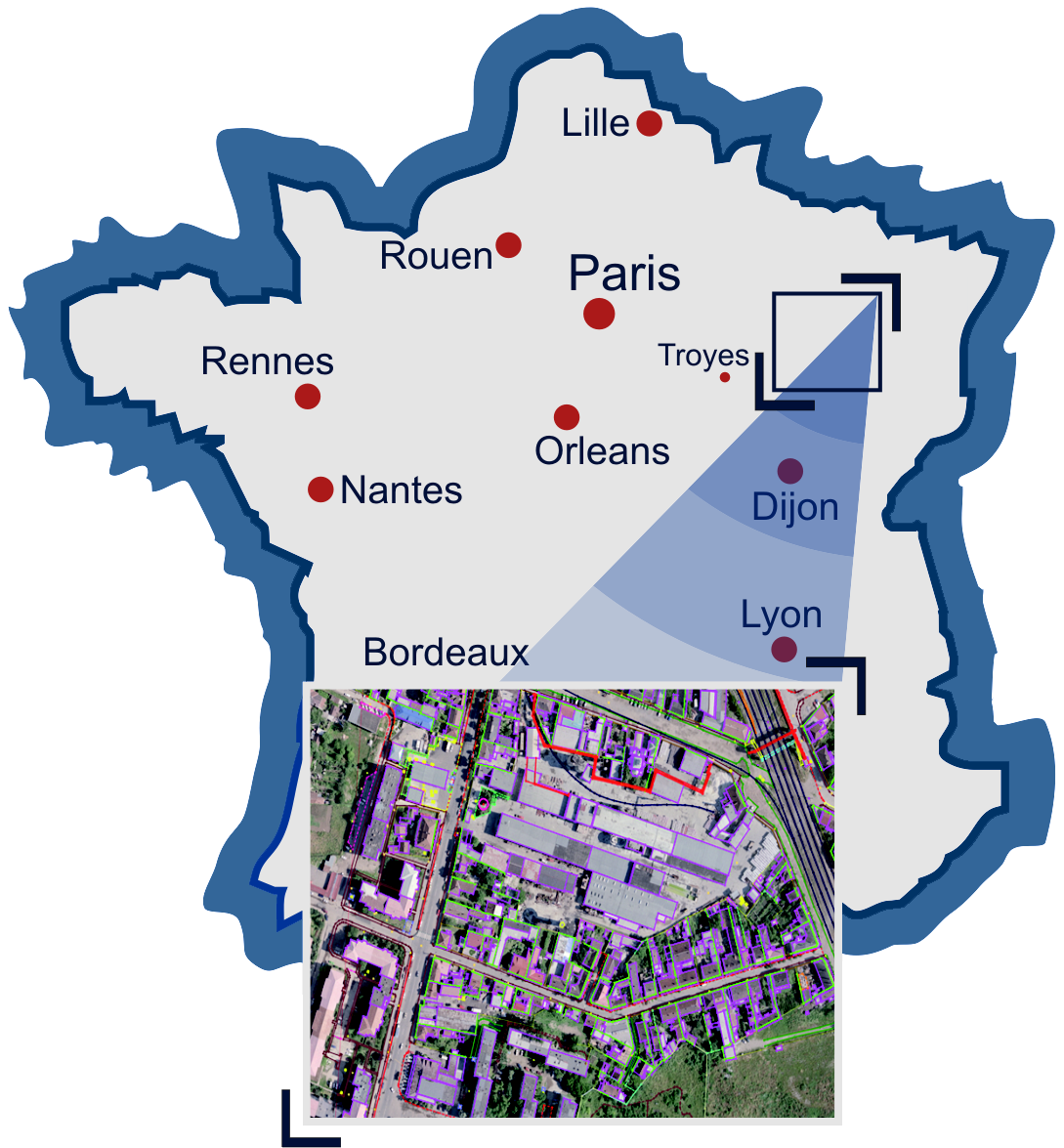
Цель — создание топографической базы данных на территорию Франции.
#—Ç–æ–ø–æ–≥—Ä–∞—Ñ–∏—á–µ—Å–∫–∞—è –±–∞–∑–∞
#—Å—Ç–µ—Ä–µ–æ–≤–µ–∫—Ç–æ—Ä–∏–∑–∞—Ü–∏—è
#–¥–µ—à–∏—Ñ—Ä–∏—Ä–æ–≤–∞–Ω–∏–µ
#—Ç–æ–ø–æ–≥—Ä–∞—Ñ–∏—á–µ—Å–∫–∞—è –±–∞–∑–∞
#—Å—Ç–µ—Ä–µ–æ–≤–µ–∫—Ç–æ—Ä–∏–∑–∞—Ü–∏—è
#–¥–µ—à–∏—Ñ—Ä–∏—Ä–æ–≤–∞–Ω–∏–µ
–ò—Å–ø–æ–ª—å–∑–æ–≤–∞–Ω–æ –ü–û:
–Ý–µ–∑—É–ª—å—Ç–∞—Ç—ã:
- –û–±—Ä–∞–±–æ—Ç–∞–Ω–æ 4,5% —Ç–µ—Ä—Ä–∏—Ç–æ—Ä–∏–∏ –§—Ä–∞–Ω—Ü–∏–∏.
- –ö–ª–∞—Å—Å–∏—Ñ–∏–∫–∞—Ç–æ—Ä —Å–æ–¥–µ—Ä–∂–∞–ª 133 –∫–æ–¥–∞.
- Точность векторизации в 3D — 1 м.
- –ó–∞–¥–µ–π—Å—Ç–≤–æ–≤–∞–Ω–æ 40 –æ–ø–µ—Ä–∞—Ç–æ—Ä–æ–≤.